4HWF SERIES
1,500 to 8,000 lb Capacity
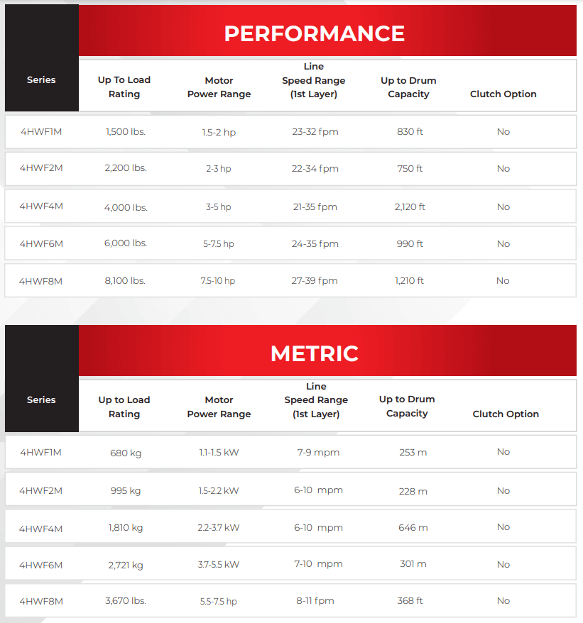
Thern 4HWF series power winches feature helical/worm gearing making them ideal for applications requiring secure load control and accurate positioning.
QUICK FACTS
- Flange style roller bearings
- Welded steel drum
- Extended solid steel drum shaft
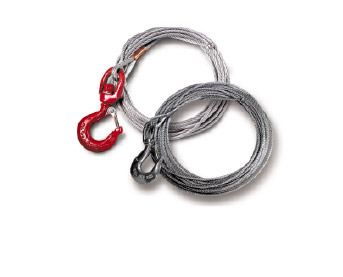
- Wire rope assemblies
- Flange mounted motor
- Load holding motor disc brake
- Direct drive gear reducers
- AMSE compliance
- 2-Year Limited Warranty
SERIES MODELS
- 4HWF1M
- 4HWF2M
- 4HWF4M
- 4HWF6M
- 4HWF8M
NEED A QUOTE?
If you’re not sure what product you need and would like a quote, please fill out a request form.
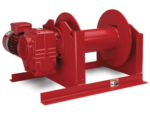
Model 4HWF1M Heavy Duty Power Winch
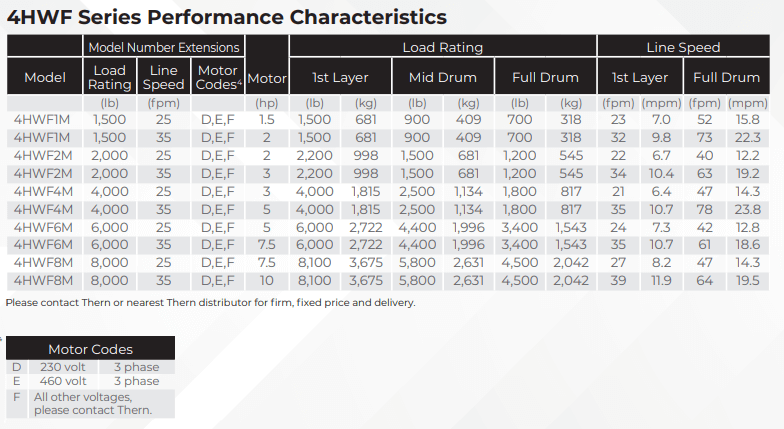
4HWF Series Performance Characteristics |
||||||||||||||
Model Number Extensions |
Load Rating |
Line Speed |
||||||||||||
Model No. |
Load Rating |
Line Speed |
Motor Codes |
Motor HP |
1st Layer |
Mid Drum |
Full Drum |
1st Layer |
Full Drum |
|||||
(lb) |
(fpm) |
(lb) |
(kg) |
(lb) |
(kg) |
(lb) |
(kg) |
(fpm) |
(mpm) |
(fpm) |
(mpm) |
|||
4HWF1M |
1500 |
25 |
D,E,F |
1.5 |
1500 |
681 |
900 |
409 |
700 |
318 |
23 |
7.0 |
52 |
15.8 |
4HWF1M |
1500 |
35 |
D,E,F |
2 |
1500 |
681 |
900 |
409 |
700 |
318 |
32 |
9.8 |
73 |
22.3 |
4HWF2M |
2000 |
25 |
D,E,F |
2 |
2200 |
998 |
1500 |
681 |
1200 |
545 |
22 |
6.7 |
40 |
12.2 |
4HWF2M |
2000 |
35 |
D,E,F |
3 |
2200 |
998 |
1500 |
681 |
1200 |
545 |
34 |
10.4 |
63 |
19.2 |
4HWF4M |
4000 |
25 |
D,E,F |
3 |
4000 |
1815 |
2500 |
1134 |
1800 |
817 |
21 |
6.4 |
47 |
14.3 |
4HWF4M |
4000 |
35 |
D,E,F |
5 |
4000 |
1815 |
2400 |
1134 |
1800 |
817 |
35 |
10.7 |
78 |
23.8 |
4HWF6M |
6000 |
25 |
D,E,F |
5 |
6000 |
2722 |
4400 |
1996 |
3400 |
1543 |
24 |
7.3 |
42 |
12.8 |
4HWF6M |
6000 |
35 |
D,E,F |
7.5 |
6000 |
2722 |
4400 |
1996 |
3400 |
1543 |
35 |
10.7 |
61 |
18.6 |
4HWF8M |
8000 |
25 |
D,E,F |
7.5 |
8100 |
3675 |
5800 |
2631 |
4500 |
2042 |
27 |
8.2 |
47 |
14.3 |
4HWF8M |
8000 |
35 |
D,E,F |
10 |
8100 |
3675 |
5800 |
2631 |
4500 |
2042 |
39 |
11.9 |
64 |
19.5 |
Please contact factory or nearest Thern distributor for firm fixed price and delivery. |
Motor Codes |
||
D |
230 volt |
3 phase |
E |
460 volt |
3 phase |
F |
All other voltages, please contact factory. |
IMPORTANT: It is the owner’s or operator’s responsibility to determine the suitability of the equipment to its intended use. Study all applicable codes, manuals and regulations. Be sure to read the Owner’s Manual supplied with the equipment before operating it.
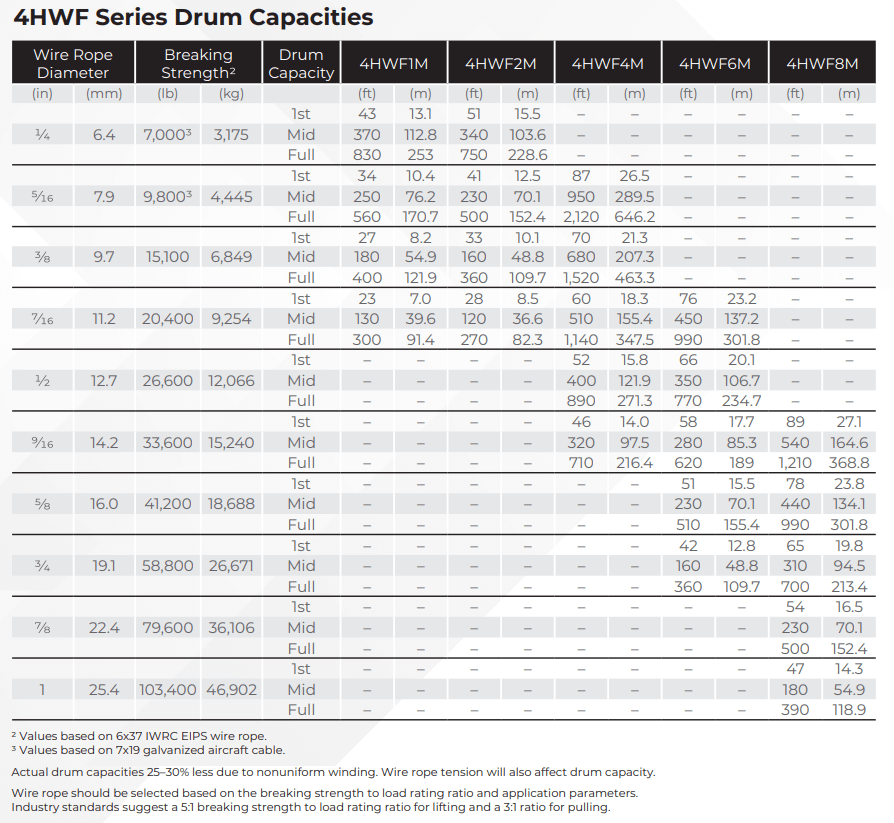
4HWF Series Drum Capacities |
||||||||||
Drum Capacity |
||||||||||
Model No. |
Wire Rope Dia. |
Breaking Strength 1 |
1st Layer |
Mid Drum |
Full Drum |
|||||
(in) |
(mm) |
(lb) |
(kg) |
(ft) |
(m) |
(ft) |
(m) |
(ft) |
(m) |
|
4HWF1M |
1/4 |
6.4 |
70002 |
3175 |
43 |
13.2 |
370 |
112.8 |
830 |
253.0 |
4HWF1M |
5/16 |
7.9 |
98002 |
4445 |
34 |
10.4 |
250 |
76.2 |
560 |
170.7 |
4HWF1M |
3/8 |
9.7 |
15,100 |
6849 |
27 |
8.2 |
180 |
54.9 |
400 |
121.9 |
4HWF1M |
7/16 |
11.2 |
20,400 |
9254 |
23 |
7.0 |
130 |
39.6 |
300 |
91.4 |
4HWF2M |
1/4 |
6.4 |
70002 |
3175 |
51 |
15.5 |
340 |
103.6 |
750 |
228.6 |
4HWF2M |
5/16 |
7.9 |
98002 |
4445 |
41 |
12.5 |
230 |
70.1 |
500 |
152.4 |
4HWF2M |
3/8 |
9.7 |
15,100 |
6849 |
33 |
10.1 |
160 |
48.8 |
360 |
109.7 |
4HWF2M |
7/16 |
11.2 |
20,400 |
9254 |
28 |
8.5 |
120 |
36.6 |
270 |
82.3 |
4HWF4M |
5/16 |
7.9 |
98002 |
4445 |
87 |
26.5 |
950 |
289.6 |
2120 |
646.2 |
4HWF4M |
3/8 |
9.7 |
15,100 |
6849 |
70 |
21.3 |
680 |
207.3 |
1520 |
463.3 |
4HWF4M |
7/16 |
11.2 |
20,400 |
9254 |
60 |
18.3 |
510 |
155.4 |
1140 |
347.5 |
4HWF4M |
1/2 |
12.7 |
26,600 |
12,066 |
52 |
15.8 |
400 |
121.9 |
890 |
271.3 |
4HWF4M |
9/16 |
14.2 |
33,600 |
15,240 |
46 |
14.0 |
320 |
97.5 |
710 |
216.4 |
4HWF6M |
7/16 |
11.2 |
20,400 |
9254 |
76 |
23.2 |
450 |
137.2 |
990 |
301.8 |
4HWF6M |
1/2 |
12.7 |
26,600 |
12,066 |
66 |
20.1 |
350 |
106.7 |
770 |
234.7 |
4HWF6M |
9/16 |
14.2 |
33,600 |
15,240 |
58 |
17.7 |
280 |
85.3 |
620 |
189.0 |
4HWF6M |
5/8 |
16.0 |
41,200 |
18,688 |
51 |
15.5 |
230 |
70.1 |
510 |
155.4 |
4HWF6M |
3/4 |
19.1 |
58,800 |
26,671 |
42 |
12.8 |
160 |
48.8 |
360 |
109.7 |
4HWF8M |
9/16 |
14.2 |
33,600 |
15,240 |
89 |
27.1 |
540 |
164.6 |
1210 |
368.8 |
4HWF8M |
5/8 |
16.0 |
41,200 |
18,688 |
78 |
23.8 |
440 |
134.1 |
990 |
301.8 |
4HWF8M |
3/4 |
19.1 |
58,800 |
26,671 |
65 |
19.8 |
310 |
94.5 |
700 |
213.4 |
4HWF8M |
7/8 |
22.4 |
79,600 |
36,106 |
54 |
16.5 |
230 |
70.1 |
500 |
152.4 |
4HWF8M |
1 |
25.4 |
103,400 |
46,902 |
47 |
14.3 |
180 |
54.9 |
390 |
118.9 |
Values based on 6×37 IWRC EIPS wire rope. 1 Values based on 7×19 galvanized aircraft cable. 2 Actual drum capacities 25-30% less due to non-uniform winding. Wire rope tension will also affect drum capacity. Wire rope should be selected based on the breaking strength to load rating ratio and application parameters. Industry standards suggest a 5:1 breaking strength to load rating ratio for lifting and a 3:1 ratio for pulling. |

4HWF Series Winch Dimensions |
||||||||||||||||
Model No. |
A |
B |
C |
D |
E |
H |
J |
K |
||||||||
(in) |
(mm) |
(in) |
(mm) |
(in) |
(mm) |
(in) |
(mm) |
(in) |
(mm) |
(in) |
(mm) |
(in) |
(mm) |
(in) |
(mm) |
|
4HWF1M-1500-25 |
25.50 |
648 |
27.00 |
686 |
6.00 |
152 |
8.00 |
203 |
2.38 |
60 |
14.00 |
356 |
1.00 |
25 |
20.00 |
508 |
4HWF1M-1500-35 |
25.50 |
648 |
27.00 |
686 |
6.00 |
152 |
8.00 |
203 |
2.38 |
60 |
14.00 |
356 |
1.00 |
25 |
20.00 |
508 |
4HWF2M-2000-25 |
26.25 |
667 |
28.00 |
711 |
6.00 |
152 |
8.00 |
203 |
2.38 |
60 |
14.00 |
356 |
1.00 |
25 |
20.00 |
508 |
4HWF2M-2000-35 |
26.25 |
667 |
29.75 |
756 |
6.00 |
152 |
8.00 |
203 |
2.38 |
60 |
14.00 |
356 |
1.00 |
25 |
20.00 |
508 |
4HWF4M-4000-25 |
39.00 |
991 |
35.00 |
889 |
9.63 |
245 |
12.00 |
305 |
5.13 |
130 |
21.00 |
533 |
1.00 |
25 |
30.50 |
775 |
4HWF4M-4000-35 |
39.00 |
991 |
35.00 |
889 |
9.63 |
245 |
12.00 |
305 |
5.13 |
130 |
21.00 |
533 |
1.00 |
25 |
30.50 |
775 |
4HWF6M-6000-25 |
41.00 |
1041 |
36.00 |
914 |
9.63 |
245 |
12.00 |
305 |
5.13 |
130 |
21.00 |
533 |
1.00 |
25 |
30.50 |
775 |
4HWF6M-6000-35 |
41.00 |
1041 |
39.00 |
991 |
9.63 |
245 |
12.00 |
305 |
5.13 |
130 |
21.00 |
533 |
1.00 |
25 |
30.50 |
775 |
4HWF8M-8000-25 |
50.00 |
1270 |
43.50 |
1105 |
12.00 |
305 |
14.50 |
368 |
6.25 |
159 |
25.50 |
648 |
1.25 |
32 |
26.50 |
673 |
4HWF8M-8000-35 |
50.00 |
1270 |
45.50 |
1156 |
12.00 |
305 |
14.50 |
368 |
6.25 |
159 |
25.50 |
648 |
1.25 |
32 |
26.50 |
673 |
Model No. |
L |
M |
N |
P |
R |
S (hole dia.) |
V |
Ship Wt. |
||||||||
(in) |
(mm) |
(in) |
(mm) |
(in) |
(mm) |
(in) |
(mm) |
(in) |
(mm) |
(in) |
(mm) |
(in) |
(mm) |
(lb) |
(kg) |
|
4HWF1M-1500-25 |
10.00 |
254 |
7.56 |
192 |
0.63 |
16 |
15.75 |
400 |
7.88 |
200 |
19/32 |
15 |
— |
— |
190 |
87 |
4HWF1M-1500-35 |
10.00 |
254 |
7.56 |
192 |
0.63 |
16 |
15.75 |
400 |
7.88 |
200 |
19/32 |
15 |
— |
— |
190 |
87 |
4HWF2M-2000-25 |
10.00 |
254 |
7.56 |
192 |
0.63 |
16 |
15.75 |
400 |
7.88 |
200 |
19/32 |
15 |
— |
— |
240 |
109 |
4HWF2M-2000-35 |
10.00 |
254 |
7.56 |
192 |
0.63 |
16 |
15.75 |
400 |
7.88 |
200 |
19/32 |
15 |
— |
— |
240 |
109 |
4HWF4M-4000-25 |
15.25 |
387 |
11.50 |
292 |
1.00 |
25 |
24.00 |
610 |
12.00 |
305 |
7/8 |
22 |
— |
— |
480 |
218 |
4HWF4M-4000-35 |
15.25 |
387 |
11.50 |
292 |
1.00 |
25 |
24.00 |
610 |
12.00 |
305 |
7/8 |
22 |
— |
— |
480 |
218 |
4HWF6M-6000-25 |
15.25 |
387 |
11.50 |
292 |
1.00 |
25 |
24.00 |
610 |
12.00 |
305 |
7/8 |
22 |
— |
— |
650 |
295 |
4HWF6M-6000-35 |
15.25 |
387 |
11.50 |
292 |
1.00 |
25 |
24.00 |
610 |
12.00 |
305 |
7/8 |
22 |
— |
— |
710 |
323 |
4HWF8M-8000-25 |
13.25 |
337 |
14.50 |
368 |
1.13 |
29 |
28.75 |
730 |
14.38 |
365 |
1-1/8 |
29 |
39.75 |
1010 |
1120 |
509 |
4HWF8M-8000-35 |
13.25 |
337 |
14.50 |
368 |
1.13 |
29 |
28.75 |
730 |
14.38 |
365 |
1-1/8 |
29 |
39.75 |
1010 |
1180 |
536 |
Dimensions are for reference only and subject to change without notice. Please contact factory for exact dimensions. |
IMPORTANT: It is the owner’s or operator’s responsibility to determine the suitability of the equipment to its intended use. Study all applicable codes, manuals and regulations. Be sure to read the Owner’s Manual supplied with the equipment before operating it.

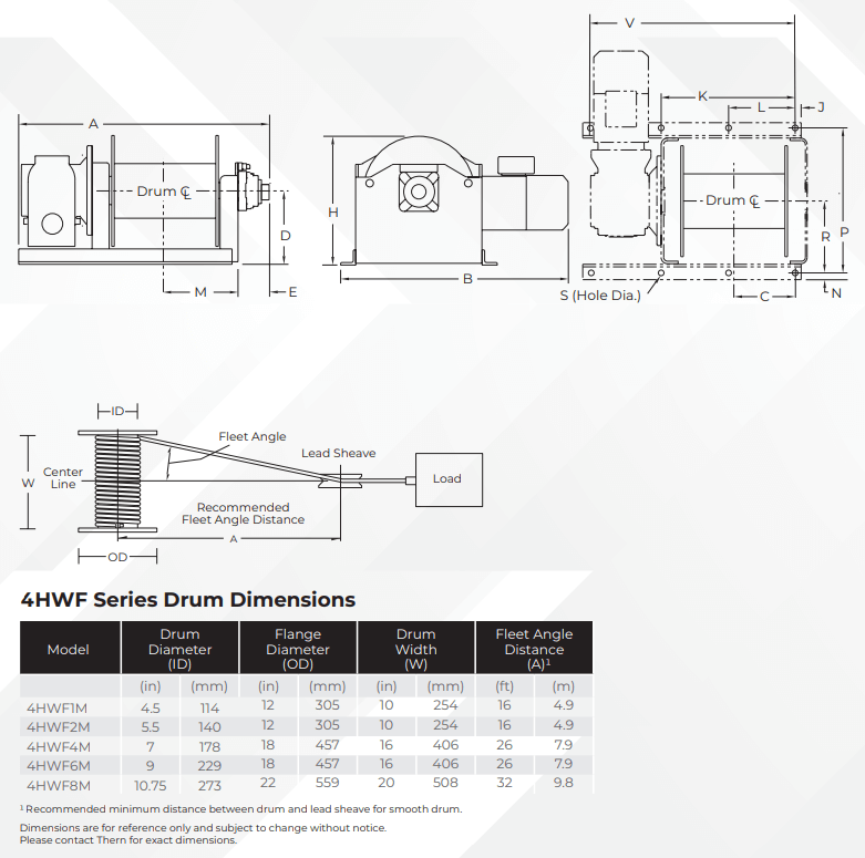
4HWF Series Drum Dimensions |
||||||||
Model Extension |
Drum Dia. (ID) |
Flange Dia. (OD) |
Drum Width (W) |
Flange Angle Distance (A)1 |
||||
(in) |
(mm) |
(in) |
(mm) |
(in) |
(mm) |
(ft) |
(m) |
|
4HWF1M |
4.50 |
114 |
12.00 |
305 |
10.00 |
254 |
16 |
4.9 |
4HWF2M |
5.50 |
140 |
12.00 |
305 |
10.00 |
254 |
16 |
4.9 |
4HWF4M |
7.00 |
178 |
18.00 |
457 |
16.00 |
406 |
26 |
7.9 |
4HWF6M |
9.00 |
229 |
18.00 |
457 |
16.00 |
406 |
26 |
7.9 |
4HWF8M |
10.75 |
273 |
22.00 |
559 |
20.00 |
508 |
32 |
9.8 |
1 Recommended minimum distance between drum and lead sheave for smooth drum. Dimensions are for reference only and subject to change without notice. Please contact factory for exact dimensions. |
IMPORTANT: It is the owner’s or operator’s responsibility to determine the suitability of the equipment to its intended use. Study all applicable codes, manuals and regulations. Be sure to read the Owner’s Manual supplied with the equipment before operating it.